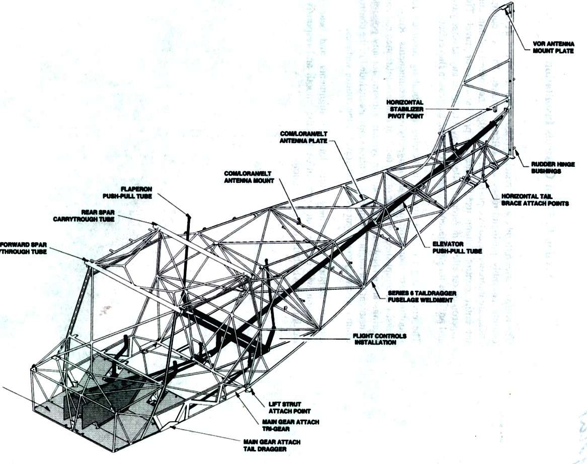
This picture is from the construction manual. It shows the controls that will be fabricated and installed.
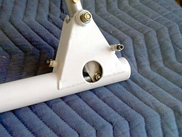
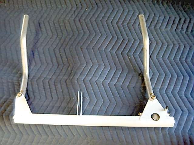
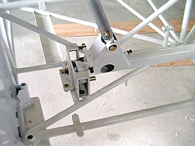
The fuselage work began with construction of the bracket to attach the control sticks. Then, the control column pivot arms were placed into their housings. This took quite a bit of machining as the bearings were pressed, limit screws tapped, and parts fabricated.
The left and right pivots on the control column were interconnected using a rod. Attachment to the right pivot was very difficult due to the tight working space. Washers needed to be sandwiched onto both sides of the rod end and the whole assembly placed into the jaws of the pivot arm. When I finally got this done, I found that the pivot arm jaws were binding onto the rod end. I removed everything, ground the jaws with a Dremel tool, and reassembled. The left side was much easier.
The control column was installed in the cockpit. It took a little machining to get the bushing on the right attachment bracket to fit properly. It is designed with the bushing slightly wider than the bearing. That way, all movement takes place between the bushing and bearing - instead of on the bolt. The bushing had to be reduced about .0003" to allow appropriate clearance for smooth movement.
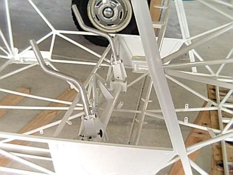
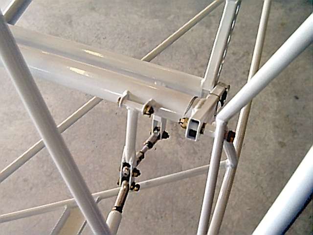
The flap handle is connected to the flaperon mixer via a push rod. Mounting the flap handle itself was difficult because other structural members interfered with the bolt head.
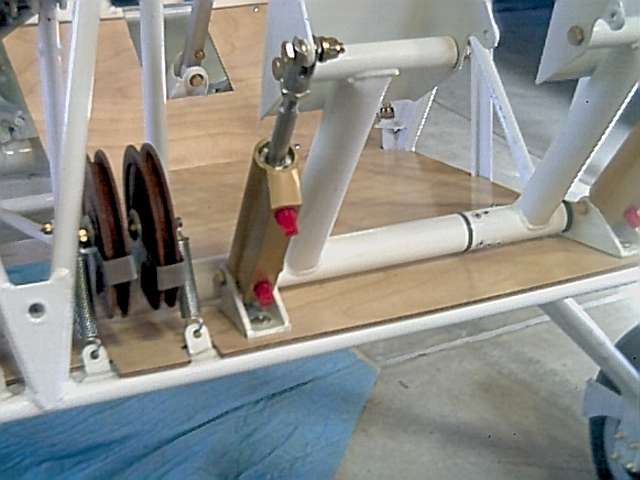
The flap connection is the lower rod end in this picture. The other connection visible here is the elevator rod attached to the idler arm.
The control column aileron bellcrank was attached to the flaperon mixer assembly. This aircraft uses a full span flaperon (instead of a conventional aileron) for both roll control and flap deflection. The mixer assembly mechanically permits the two separate controls to work on the same surfaces.
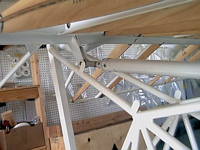
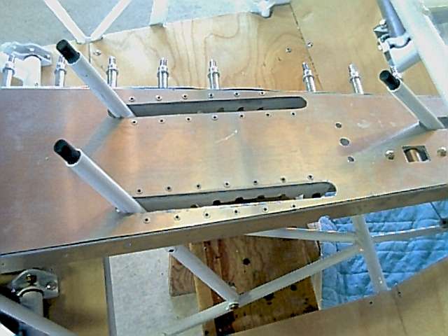
These pictures show the elevator push rod attached to the idler arm and the elevator bellcrank. The rod was built from aluminum tubing. A threaded rod end was attached on each side with rivets and epoxy. The rod is fed through the center of the rear fuselage where it is supported by a bushing in the middle of the span.
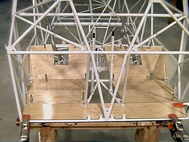
The cockpit floorboards are made out of thin (2.5mm) birch plywood. There are five separate boards making up the floor. The parts were first fit using a cardboard template then the plywood was cut. You don't want to mess up these cuts, as the cost for replacement plywood for these five pieces is about $100.00. Two coats of epoxy varnish were applied to the plywood and the boards were attached to the fuselage with panhead screws.
Rudder Pedals Mounted
The rudder pedal assemblies were built and mounted to the cockpit floor. Extra steps were required because I am installing adjustable rudder pedals. This feature will allow repositioning the rudder and brake pedals for individual pilot height. After all, the seats do not move and cannot be adjusted.
The center console was cut, deburred, and countersunk for rivets. The microstop countersink worked well for this task. David did the rivet installation to attach the flap handle and adjustable rudder handle detent brackets to the top. The top was then attached to the console and the sides were cut, fit, and drilled. The rear attach points for the top were elevated with AN460-10 washers. Trimming the .016 sheet metal for the sides was best performed with the pneumatic shears. The pilot's rudder adjustment handle detents required tooling to get a smooth action. There was initially tighntess and interference at the rear arc of travel.
Seats
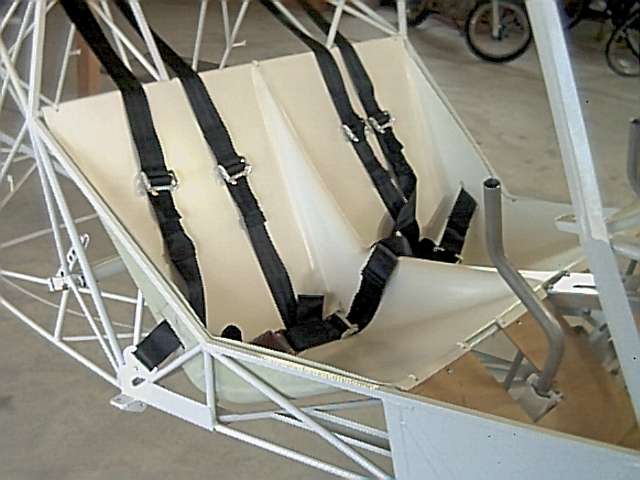
The fiberglass seat pan was trimmed and installed. These buckets will be covered by upholstery and cushions during the finishing stages. Seat belts were bolted to the appropriate attach points.
Main Gear
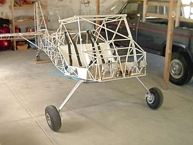
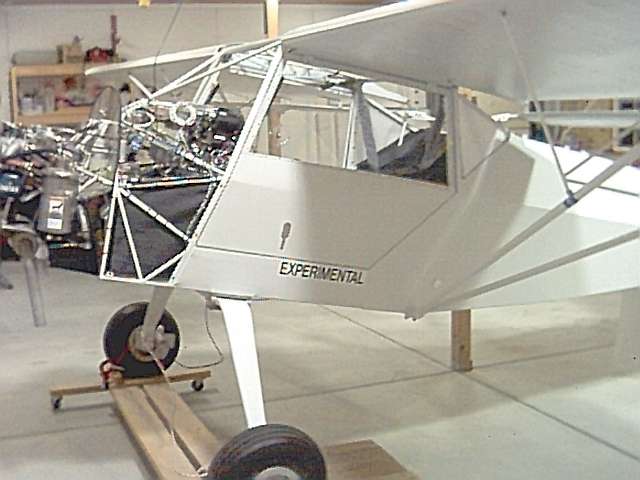
I placed the fuselage on to the landing gear so it would be easier to move around. Main gear is made of spring aluminum. Wheels and brakes are Cleveland. The tailwheel is made by Maule.
Brake Master Cylinders
The back-ordered brake master cylinders finally arrived. They were Matco cylinders instead of the originally specified Cleveland cylinders. Skystar cited problems with Cleveland delivery for the replacement. I have decided to order a Matco parking brake valve and install it prior to running all the hydraulic lines. This low cost (approximately $100) option was brought to my attention in one of Tony Bingelis' books.
The rudder cables were installed. The cable originally provided by Skystar was too short, but they sent a new cable to make up the difference for no additional charge. The attachment and cable routing was a little bit tricky because of the adjustable pedals. Cable ends were swaged with a Nicopress sleeve and heat shrink tubing. Final attachment to the rudder horn will not be done until the fabric is installed.
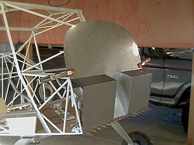
Firewall Fabrication
The firewall is made of stainless steel. I came as several sections which had to be cut, fit, and rivetted. Final installation will not be done until the fuselage is fabric covered. The initial trial fitting shown here was required so that attachment clips could be mounted on the belly prior to fabric. The floorboards and rudder pedals had to be removed to perform this step.
The doors are welded frames which hinge at the top. The bottom of the door is covered with a fiberglass panel. The window is polycarbonate. A single latch is used to hold the door closed on the bottom.
Cargo Area
The cargo area is located directly behind the seats. A rather complicated nylon sack encloses the area and is attached to structural tubing with velcro. The floor of the main cargo area is a wood faced honeycomb composite. Smaller side areas in the cargo sack are intended for headset storage.
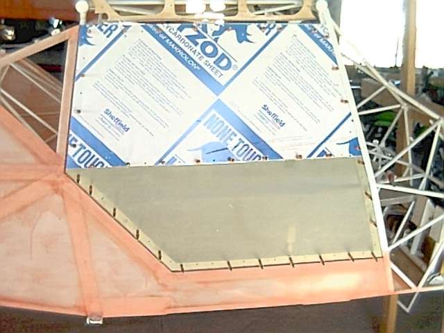
The rear window, mounted in a frame and refered to as the turtledeck, is removable so that the flaperons can be disconnected and the wings folded. Camlock fasteners make removal simple.
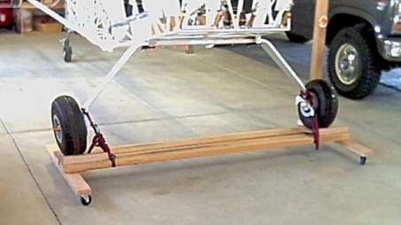
Landing Gear
The main wheels are mounted on a single piece spring aluminum gear. The brake line runs through the center of the gear. The main gear can be mounted forward (for a tailwheel configuration) or rearward (for a tricycle configuration). This picture shows the gear resting on the dolly that I made to facilitate movement of the aircraft while in the shop.
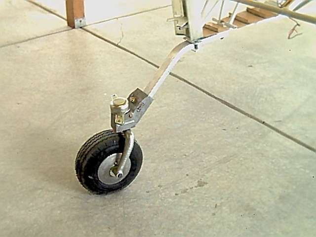
The tail wheel is mounted at the end of an aluminum spring. The tire is pneumatic.
 Fuselage