Jump To:
Home Page
Builder Biography
Kitfox Information
Preparing to Build
The Tail
The Fuselage
The Wings
Fabric Covering
Instrument Panel
Cockpit Interior
Engine Installation
Transport Trailer
Done?
Flight
Alaska Flight
Discoveries
Building Tips
Download Page
|
|
Building the Empennage
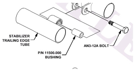
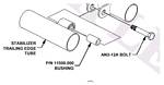
Empennage construction began with preparing the horizontal stabilizer. The elevator bushing attach points needed to be reamed to .4375". This was complicated because the structural tubing interfered with turning the reamer. To overcome this, I tapped the end of the reamer bit (3/8") and attached it to a threaded steel rod with a 'T' handle. This allowed me to reach all seven locations.
Modifying the tool and reaming the seven points took 1.5 hours.
|
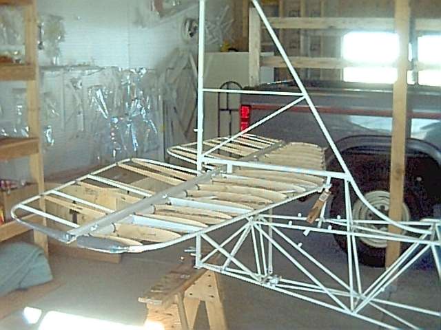
Ribs In Elevator and Stabilizer
Several plywood ribs needed to be placed in the elevator and horizontal stabilizer. After fitting, the ribs were glued in place with a structural epoxy. These ribs ultimately give an airfoil shape to these control surfaces. The epoxy will cure in three days at 77 degrees.
|

|
|
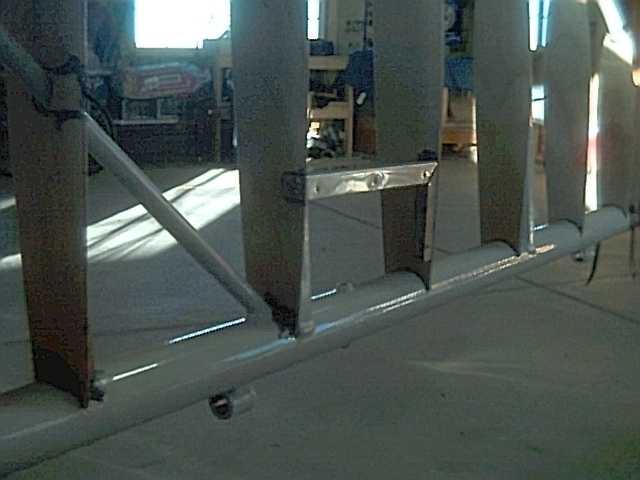
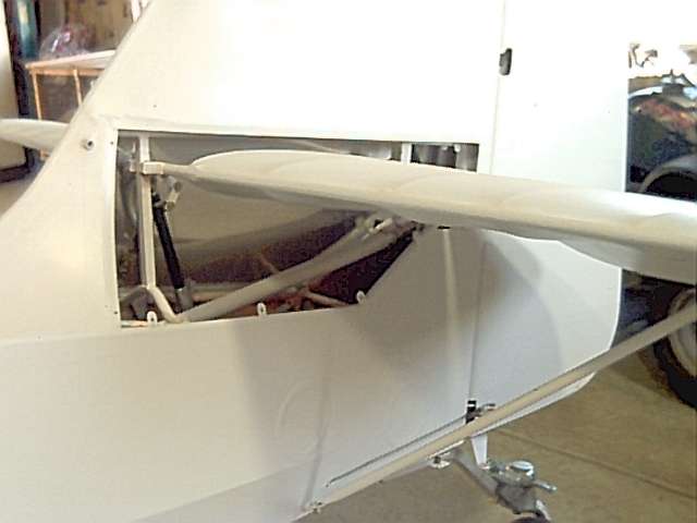
Frame for Access Panel
Once all the plywood ribs were installed, they were covered with epoxy varnish (two coats). This will help minimize warping and swelling with humidity changes.
The aluminum frame pictured here was fabricated and installed. This frame provides an access panel to the attach points where braces enter the horizontal stabilizer.
|
Tip Treatment
Foam blocks have been epoxied to the tips of the elevator and horizontal stabilizer. These blocks will be shaped into a pleasing profile to provide smooth edges.
|
|
|
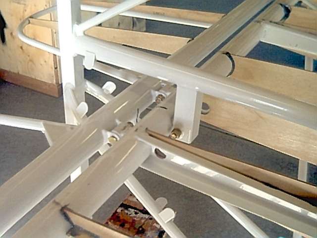
Installing the Elevator
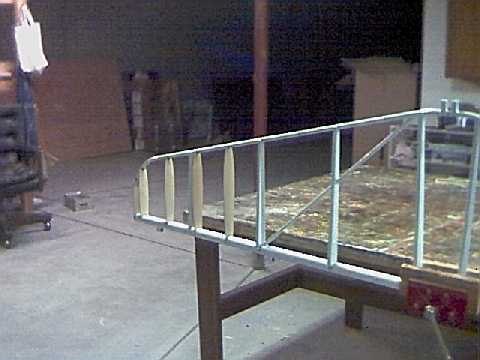
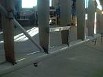
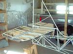
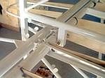
The horizontal stabilizer was installed on to the fuselage. The stabilizer pivots from the rear. In this manner, the angle of incidence can be changed to adjust the pitch trim. The front of the elevator straddles a guide tube to keep it aligned. There are external braces underneath both sides of the stabilizer.
The trim is controlled by an electric jack screw. The screw extends and retracts to raise and lower the leading edge of the horizontal stabilizer. The present location of the screw is telegraphed to the cockpit with a control cable.
The elevator was then attached to the stabilizer.
|
Elevator Hinge
The elevator hinge attaches in six places. AN3 bolts are used for the hinge pins. My initial installation resulted in an overly snug fit - the hinge tabs were pinching the bearings. I resized the gaps by filing the powder coating and slightly spreading the tabs.
|
|
|
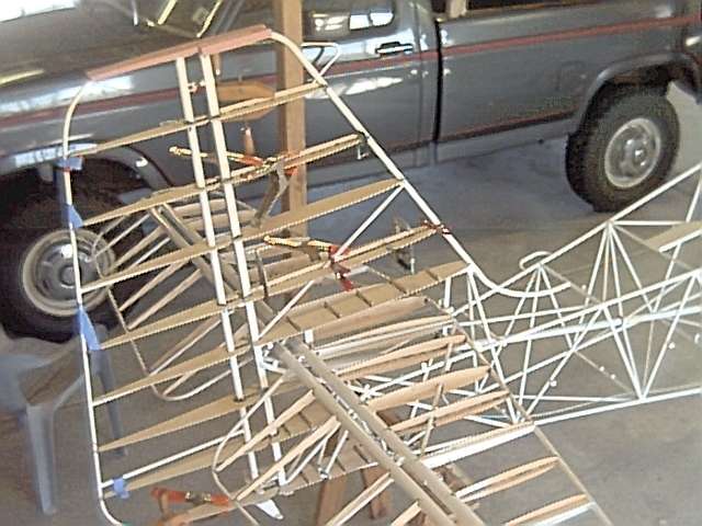
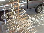
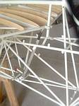
Rudder Installation
The rudder has been temporarily installed. The plywood airfoil shaped ribs are shown being glued into the rudder and the vertical stabilizer. These airfoil shapes are an option for the kit. A bulkhead, also made of plywood, was attached to the area just in front of the horizontal stabilizer. The tips of all surfaces were shaped with foam and epoxy.
|
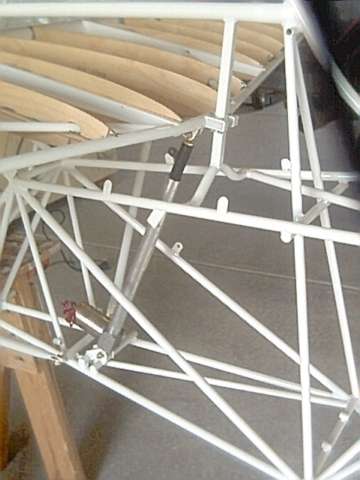
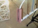
Trim
Elevator trim is performed by an electric jackscrew raising and lowering the leading edge of the horizontal stabilizer. Control of the jackscrew is with a toggle switch in the cockpit. Trim position is transmitted via a mechanical cable to an indicator spring/guage.
|
|
|
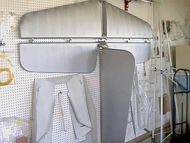
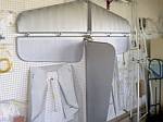
Tail Feathers are Coverered
Once all the empanage parts were covered with fabric, they were sprayed with UV protective coating and painted. Here they await final assembly to the aircraft.
|
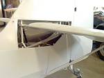
Access Panel
When all the parts are assembled, access panels are fabricated out of aluminum to provide future maintenance availability.
|
|
|
 Builder's Log - Tail Section